There's all kinds of stuff going on today as I try to get the apparatus ready to go to measure the amplitude of the magnetic field required for levitation at each frequency.
First, the levitation detector on the sample holder.
Building the levitation detector on the sample holder and the liquid nitrogen reservoir didn't work out nearly as well as I'd hoped that it might. First you ask, what's a levitation detector? Up until now, I've been determining the moment of levitation after the experiment by making videos that watch the superconductor as the AC magnetic field is increased. This was fine until I wanted to know what the magnitude of the voltage seen on the pick-up coil used to detect the levitation magnetic field was at the exact moment the superconductor first levitated. There were a number of problems with doing this with cameras, the least of which was actually needing two cameras.
I came up with a system of attaching a piece of aluminum foil to the boom, (the Bic pen portion of the torsion balance), and supporting the boom on the points of two wires. The two wires were connected to five volts and and one of the digital inputs of the Arduino respectively. When the superconductor was not levitating, the aluminum foil on the boom would sit on the two wires completing the circuit and maintaining a digital high input on the Arduino pin, (see the picture below). When the superconductor levitated, the aluminum foil on the boom was lifted off the two wires, the connection was broken, the Arduino saw a digital low input and subsequently lit an LED. This mechanism made or broke a connection to a five volt source that the Arduino system could watch. When the connection was broken, the Arduino turned on an LED.
I had intended to make a brief video this week showing that liquid nitrogen does not conduct, (I did by the way), but I got a lesson on the conductance of water vapor this morning. The short version of the story: distilled or pure water does not conduct. The two wires shown above near the pivot of the boom were originally placed on the edge of the reservoir. That close to the liquid nitrogen, there was a significant build-up of ice on the contacts. As the ice built up, the switching mechanism stopped working. Moving the entire switch back on the boom fixed the problem. A picture of the reservoir edge configuration is shown below.
You might also notice that the final implementation has one of the contacts cupping the boom. With the two point configuration, the boom could acutually rest on one point without making contact with the other.
Modifying the Pick-Up Coil
The original pick-up coil was abandoned for a coil that could be used during the experiment. The original coil had to be moved on and off of the magnet and with the initial lev switch on the reservoir implementation, this was no longer convenient. The pick-up coil now consists of two turns of wire wound directly on the magnets windings at the top of the magnet.
Actual Data!
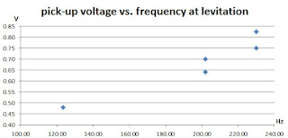
Finally, late in the afternoon, most of the switch issues were worked out and the data shown below was taken. The graph shows the peak voltage measured from the pick-up coil when levitation was obtained. For the frequencies where there are two points, the lower voltage is where levitation was first achieved, as detected by the blinking activation of the LED. The higher voltage is where steady levitation was achieved as indicated by the steady activation of the LED. So far, there are only three frequencies, more work will be done to fill in the gaps.
The voltage measured should be proportional to the magnetic field. This needs to be calibrated. For now, the data gives a good idea of the relative relation between required field strength and frequency.
Procedure:
The torsion balance rests on a laboratory jack. The jack is lowered before each measurement until the LED indicating that the boom has risen off the switch activates. The jack is then raised until the LED is extinguished. This is done to minimize the distance the superconductor must be levitated to activate the LED.
The superconductor is allowed to transition to room temperature for three minutes between measurements. The superconductor is immersed in liquid nitrogen for three minutes before each measurement is taken. The heating cycle is included to remove any pinned flux in the superconductor that might be present from the previous measurement.
Sources of error:
The jack adjustment is may change the height of the superconductor with respect to the magnet. There is a known dependency between levitation force and the distance between the superconductor and the magnet..
Ice is building up on the sample holder during some runs. This will change the effective mass that is to be levitated by the magnetic field.
Heated Ferromagnetic Core
At one point during the day, there appeared to have been too much heating of the electromagnet's core. The waveforms measured by the pickup coil for the overheated core are shown below:
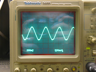
and now the waveform form the pickup coil when the core wasn't overheated:
I believe the overheated waveform was due to hysteretic losses in the core, but I'm not sure and more work needs to be done to confirm this.
Random data notes
1080 601 - 100 Hz. minimum steady lift
1080 605 - 200 Hz. first lev
1080 607 - 200 Hz. first steady lev
no lev at 300 Hz moving to 25 Hz increments about 200 Hz.
1080 610 - 225 Hz. first lev also steday lev
250 Hz. no lev


Comments
Post a Comment
Please leave your comments on this topic: