 While doing research for the NMSU Superconductor Gravity Experiment, I came across an article published by J.E. Hirsch of UCSD. He writes that his 'hole theory of superconductivity', (more on this in a later post), predicts that x-ray photons should be emitted by a superconductor similar in size to our sample when it changes from the superconducting to the non-superconducting state. The superconducting sample I'm using cycles between states each time a set of levitation force data is taken, so I decided to go ahead and try to detect the radiation predicted by Dr. Hirsch as a side project. A Geiger counter is being used as the radiation detector because it was readily available. Data acquisition with the Geiger detector turned out to be a little more work than I expected.
My first thought was that I could simply record the beeps coming from the Geiger counter and then use Audacity to analyze the resulting audio file. There were a few issues that cropped up with this method though. First, it's not immediately obvious that two or more beeps close to each other can be distinguished from a single beep. In the waveform shown below, the bigger the peak, in general, the more beeps occurred at that time, but not always. The second issue was that it seemed somewhat likely that the audio recorder being used was 'helpfully' increasing the amplitutde of the beeps so that they could be heard above other transient noises like the magnets power supply fan. If that were the case, then single beeps could easily be interpreted as multiple beeps. Given these issues, the audacity data analysis scheme wasn't going to work.
 |
|---|
Arduino to the Rescue
Since the audio data wasn't going to cut it, we needed to get closer to the source. The next idea was to capture the signals that drove the piezoelectric buzzer on the Geiger counter. The signal turned out to be a five volt digital waveform. By sampling the line driving the buzzer, we could wind up with a graph of beeps vs. time. The only question left was how to sample the data in a cheap and simple way. A few months back, I purchased an Arduino kit from dalewheat.com. For those of you that don't know, the Arduino is a microcontroller board and associated programming interface that was designed to make microcontroller projects accessible to not only engineers, but also to casual users like artists and performers. I purchased my little kit to play with, not knowing exactly what I would do with it. When it came time to sample the Geiger counter output however, I remembered that the Atmel ATmega382 on the Arduino board had several analog to digital convertors, (ADCs), that might fit the bill perfrectly.
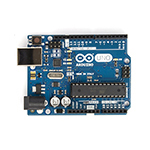
I setup my kit as shown below. The Arduino board shown above is one of the 'official' boards that you can purchase pre-assembled. My little kit from Dale Wheat, has a much simpler construction. The analog supply for the ATmega382 is just bridged over from the digital supply. The ATmega382 documentation goes on at lenght about seperating the digital and analog supplies to reduce noise, and they're right, but for this project, the simple digitial supply bridge did just fine.

|
|---|
To test the board I built a low current voltage divider circuit between teh supply rail and ground and used the divided voltage as my test input. The ADC on the ATmega382 has a 10 bit resolution. That means that there are 1023 steps between 0 volts and the maximum voltage, in this case, 5 volts. My voltage divider consisted of two 51 k-ohm resistors in series. The high resistance value was chosen to avoid pulling too much current from the power supply. The voltage at the point between the two resistors should have been 2.5 volts. I browsed through the Examples/Basics menu in the Arduino software and found an example that writes back values from the ADC to the serial port connecting the Arduino and the laptop. I uploaded the example to the memory on the ATmega382 and started it. The value printed on the serial monitor coming back from the Arduino board was 503. Scaling this by 0.0048 V per ADC step gave a result of 2.458 V, about 1.6% off from the expected value of 2.5 V and well within the expected margin of error since I was using 5% tolerance resistors.
The next step was to attach the ADC to the Geiger counter. A quick review of the onliine schematic diagrams for the Geiger counter showed where to hook into the speaker output:
 |
|---|
Using the excellent serial package for Python, I was able to write a few short lines of python code to grab the Geiger counter data and store it in a file:
import serial
import datetime
from datetime import datetime

ser=serial.Serial(2)

testout = open("testgeig3.out", "w")

for k in range(0,1000000,1):
 tester = ser.readline()
 hour = datetime.now().hour
 minute = datetime.now().minute
 second = datetime.now().second
 microsecond = datetime.now().microsecond
 #print str((hour*360)+(minute*60)+second) + "." + str(microsecond) + "," + tester
 testout.write(str((hour*360)+(minute*60)+second) + "." + str(microsecond) + "," + tester +"\n")
ser.close()
testout.close()
A note about using serial ports: I found rather confusing documentation that seemed to indicate that another serial port, (other than the one provided by the existing USB interface shown), needed to be setup on the Arduino to bring ADC data out of the chip. With the Arduino kit I have from DaleWheat.com, this wasn't the case. I was able to read the ADC data back over the same serial port.
A, (very little), bit of data massaging in Excel, and the following graph of counts, (represented as ADC voltage spikes), with respect to time, (in seconds), was generated:
 |
|---|
Comments
Post a Comment
Please leave your comments on this topic: